Fill and squeeze
On the intake stroke, the descending piston draws the fuel–air mixture through the open intake valve. During compression, both valves close and the rising piston reduces the occupied volume.
Open a detailed engine, turn its crank, and take the assembly apart. Follow four different jobs hidden inside two very similar-looking turns.
Enable JavaScript to change the conditions and run the interactive experiment.
A four-stroke engine fills, squeezes, expands and clears. The piston goes down and up twice while the crankshaft turns twice. A timed valve mechanism makes those similar-looking movements do different jobs.
After one complete crank turn, has everything returned to the starting state?
The piston position repeats after 360°, but the four-stroke sequence repeats after 720°.
On the intake stroke, the descending piston draws the fuel–air mixture through the open intake valve. During compression, both valves close and the rising piston reduces the occupied volume.
Near the end of compression, a spark starts combustion. The expanding gas does work on the descending piston. The next upward stroke pushes exhaust out through the exhaust valve. The flywheel stores rotational energy across the cycle.
This overhead-valve teaching assembly shows a camshaft, followers, pushrods and rockers. A 2:1 timing drive makes the cam turn once for two crank turns. Rockers transmit the pushrod motion to valves in the head. Small engines used in mowers provide a familiar application.
The cutaway removes the front of the cylinder wall to expose the piston. In the exploded view, the head, piston, rod, flywheel and cover separate along inspection directions. Return to the assembled or cutaway view before interpreting connected motion; separated parts are not operating positions.
The crank pin follows a circle, but the piston must remain on a straight guide. With crank radius r and rod length l, downward travel from the top is r+l−r cos θ−√(l²−r² sin² θ). Here r=30 mm and l=120 mm. At 90°, travel is about 33.81 mm, slightly more than halfway down.
At 0° and 360° the piston is at the top. At 0° intake is about to begin; at 360° expansion is about to begin. The complete ideal sequence repeats at 720°. The study diagram separates crank angle from stroke identity.
You supply the crank motion in this model. Removing the spark removes the combustion cue while the externally turned mechanism still moves. Actual speed, torque, pressure, fuel consumption and stalling require combustion and rotational-dynamics models.
The visible cam surface is derived from a radial roller-follower pitch curve. Its prescribed lift rises and returns smoothly during one ideal stroke. A fixed-length pushrod and rocker determine the valve lift. Roller size, cam lift and link dimensions are teaching design choices, not measurements from a commercial engine.
A small four-stroke engine can supply rotating mechanical power to different loads. The blade, generator or pump does a different job downstream; the piston, connecting rod and crankshaft still provide the same basic conversion.
A single-cylinder engine makes the whole cycle easy to inspect. Multiple-cylinder arrangements place power events at different crank angles. Two-stroke and compression-ignition engines require different explanations; this model does not substitute for them.
Make a disk with a central axle and a crank pin away from the center. Connect a long strip to the crank pin and a small card slider to its other end.
Tape two parallel card rails around the slider. Leave enough clearance for it to move. Turn gently; adjust the guide if the card binds.
Mark the slider position at 0°, 90°, 180° and 270°. Compare the first quarter-turn travel with the second. The guide makes the rod tilt as well as move.
Can a turning disk make something travel in a straight line?
A hand-powered motion model only: no fuel, combustion or pressure. An adult prepares holes and cutting. Card flex and joint friction affect movement; the physical adaptation has not yet been trialed.
Piston position, but not the entire cycle Position repeats after 360°. Intake and compression have finished, but power and exhaust are still ahead. The complete cycle requires 720°.
Neither valve Both valves are closed while the piston reduces the mixture’s volume. An open valve would allow gas to leave instead of following this sealed compression stage.
Once, in the opposite direction Two crank turns advance 40 teeth. That is one full revolution of the 40-tooth cam gear. Directly meshing external gears turn in opposite directions.
One end follows a circle while the other follows a straight line The crank pin follows a circle. The cylinder guides the piston on a straight axis. Pivoting at both ends lets a fixed-length rod connect those different paths.
The valve spring The cam and linkage push the valve open. The compressed spring returns it toward its seat as the cam lift falls. The piston does not pull the valve.
Chemical energy transferred during fuel combustion The spark starts combustion. The fuel–air reaction transfers chemical energy; expanding hot gas can do work. The crankshaft transmits motion and torque rather than creating energy.
Store and release rotational kinetic energy A rotating flywheel stores kinetic energy. Its speed can fall as it supplies work and rise as energy is added. This animation prescribes speed, so it does not calculate that variation.
The displayed motion is supplied externally; stalling is not modeled You supply the crank motion here. Omitting the spark removes the ignition cue. Predicting whether a real engine slows or stalls requires an energy and rotational-dynamics model.
The downstream load and purpose of the shaft’s rotation The engine still follows its cycle. Its output shaft drives a different load: a generator converts mechanical input to electrical output, while a pump transfers energy to fluid. Load effects need their own model.
Manufacturer explanation of intake, compression, power, exhaust and flywheel role.
Briggs & Stratton · Four strokesOriginal manufacturer video. Reference for architecture, not copied footage or model geometry.
Briggs & Stratton · Valve trainTechnical education on ideal compression, heat input and expansion. No efficiency or horsepower prediction is made here.
NASA Glenn · Otto cycleManufacturer exploded assembly reference for the relationship of parts. Original teaching geometry is used; no Honda diagram or CAD is redistributed.
Honda · GX120–200 assemblyIndependent subject review is pending.
Read the sources and model assumptionsTurn once. Count what happens. Discover gear ratios, real-world uses, and why different jobs need different gears.
 Interactive exploration
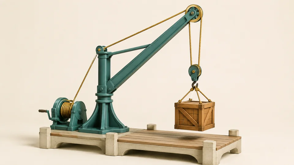
Rerig a dock crane. Pull the same length of rope, watch the crate rise, and see what you trade for an easier lift.
Power a motor. Reverse its direction. Add a load and watch speed, current and turning force find a new balance.