INTERACTIVE EXPLANATIONHow does electricity make a motor spin?
Power a motor. Reverse its direction. Add a load and watch speed, current and turning force find a new balance.
Enable JavaScript to change the conditions and run the interactive experiment.
Make a discovery
A magnetic field pushes on current-carrying wires. Arrange those pushes around an axle and they create torque. A brushed motor switches its rotor connections as it turns, keeping the turning effect going.
Make a prediction
At the same supply voltage, what happens when this motor’s load increases?
- It slows and draws more current
- It speeds up and draws less current
- Nothing changes
Read the explanation
Slower rotation produces less back EMF. More voltage is left across the winding resistance, so current and motor torque increase. Compare light and heavy drag after the same running time.
Understand it
The parts that stay and turn
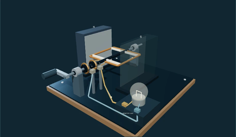
Permanent magnets belong to the stator, which stays fixed. The rotor carries coils and a shaft. Brushes stay still against a segmented commutator attached to the rotor. The 3D view separates these roles with a transparent enclosure.
A turn changes the current
As the rotor moves through the magnetic field it also acts as a generator. Its back electromotive force, or back EMF, opposes the supply. Current falls as speed builds. Reverse the supply and the average torque and rotation reverse.
What a load changes
The virtual load is a viscous brake: its opposing torque is proportional to speed. More drag leads to a lower settled speed and a larger current. A real fan often has a more strongly speed-dependent load, so this is a motor rig with a fan-shaped shaft marker, not an airflow prediction.
Look closer at the science
A coupled model
I = (V − kω)/R; τ = kI; J dω/dt = τ − bω. Here k = 0.03 N·m/A = 0.03 V·s/rad, R = 2 Ω and J = 0.002 kg·m². These are illustrative constants. Inductance, brush drop and torque ripple are omitted.
A solution you can inspect
For a start from rest, ω∞ = (kV/R)/(b + k²/R) and T = J/(b + k²/R). Then ω(t) = ω∞(1 − exp(−t/T)). The shaft angle is the integral of this expression. Negative supply produces the mirrored response.
Power has destinations
VI = I²R + τω. Mechanical power changes rotational kinetic energy and is dissipated by drag. The steady balance is kI = bω. A stalled real motor can overheat; this model does not calculate temperature or safe operation.
Try it yourself: Make a paper commutator
Supplies
- 1 sheet of paper
- 2 differently colored pencils
- A small paper arrow, folded by hand
- Draw the connections
Draw two semicircular contacts with gaps between them. Mark two fixed brush positions on opposite sides. Use one pencil for the positive brush and one for the negative.
- Turn the rotor on paper
Place your paper arrow across the circle to stand for the rotor. Rotate it half a turn. Notice that each rotor contact now meets the opposite fixed brush.
- Explain the switch
Sketch a wire loop connected to the contacts. Trace how its current reverses relative to the loop each half-turn. Compare with the motor’s mechanism view. This drawing shows switching, not an operating motor.
Can you keep a turning effect pointing the same way as a coil turns over?
A conceptual paper model: it does not create a magnetic force or reproduce a real commutator’s contact timing. No electrical supplies are needed.
Sources and model limits
- An averaged permanent-magnet brushed DC model; the three-coil drawing illustrates commutation but does not calculate individual coil currents or magnetic fields.
- No supply switching transient, inductance, saturation, brush wear or thermal model. A condition change restarts from rest.
- The 3D shaft turns at 1/30 of calculated angular motion for visibility. Speed readouts remain physical model values; camera motion is separate.
- Three.js geometry is original and schematic, not manufacturer CAD. The application marker is not an aerodynamic simulation.
Current-carrying conductors experience magnetic forces; brushes and a commutator maintain motor rotation.
University Physics Volume 2 §11.5, Fig. 11.15 and current-loop torque derivation. Supports component roles, not the exact three-coil geometry.
OpenStax · Magnetic torqueBack EMF grows with motor speed and reduces armature current.
College Physics §23.6, motor circuit and loading discussion. The constants and exact zero-inductance solution are Brytalearn teaching choices.
OpenStax · Back EMFNet torque changes angular momentum; rotational work obeys power = torque × angular velocity.
University Physics Volume 1 §10.8, rotational work and power. Supports the mechanical and energy balance.
OpenStax · Rotational powerIndependent subject review is pending.
Read the sources and model assumptions