Design a shape
Our miniature display stand has two legs, an opening and a sloping top. Its surface is a closed mesh of 28 triangles. Those triangles describe a solid boundary; they do not tell a nozzle where or when to move.
Turn a miniature stand, slice its real geometry and watch material paths build it. Solve a support puzzle, inspect actual fracture images, and take your design and learning notebook home.
Enable JavaScript to change the conditions and run the interactive experiment.
A shape describes what you want. A path plan describes how to build it. Turning the same shape can change that plan completely.
Can you reduce the stand’s layer count without shrinking the object?
The build height changes from 28 mm to 20 mm; the intended volume stays the same.
Our miniature display stand has two legs, an opening and a sloping top. Its surface is a closed mesh of 28 triangles. Those triangles describe a solid boundary; they do not tell a nozzle where or when to move.
The upright stand is 28 millimeters tall. On its side it is 20 millimeters tall. The object keeps the same ideal solid volume. What changes is the direction in which the machine will add layers.
This studio intersects the shape with horizontal planes. It places wall paths around each outline, skin paths near upper and lower surfaces, and more widely spaced paths inside. The first roof over the opening needs attention even though it is not the object’s first or last layer.
In material extrusion, feed material passes through a nozzle and is deposited along a route. In our preview, green means walls, gold means surface skin and copper means sparse interior paths. A blue dashed move is travel without added material. Colors explain roles; they do not mean different plastics.
Additive manufacturing makes a part by adding material according to a digital model. Material extrusion is the family explored here. Filament-fed FFF, or fused filament fabrication, is one familiar example. Other processes form layers in different ways; a moving filament nozzle is not a definition of every 3D printer.
At 0.2 mm per layer, 28 ÷ 0.2 gives 140 layers upright and 20 ÷ 0.2 gives 100 on the side. A thinner layer samples the build direction more finely. It does not automatically refine a nozzle’s sideways width. Our sloping top rises 4 mm over the chosen stand width; with the 40 mm stand, a 0.2 mm layer gives a 2 mm horizontal stair tread.
For layer k starting from zero, this studio takes the outline at (k + ½)h and represents a slab from kh to (k + 1)h. The nozzle’s nominal Z is the slab top. For the default first roof, those values are layer index 100, slice height 20.1 mm and nozzle Z 20.2 mm. The ideal midpoint staircase differs from the sloping surface by at most h/2 in height; that mathematical bound is not a printer accuracy specification.
The Slic3r flow explanation approximates a supported bead as a rectangle with two semicircular sides. Its area is A = h(w − h) + πh²/4, with width w at least height h. Our 0.45 mm wide, 0.2 mm high bead gives 0.0814159 mm². A 100 mm depositing move requests 8.14159 mm³; through a 1.75 mm diameter filament, that is 3.38488 mm of input filament. The same assumption gives dense-path spacing A/h. This is a flow calculation, not a measured bead shape or a hanging-bridge law.
Walls follow the perimeter. Surface skin covers regions where the object ends above or below. Sparse infill occupies an interior region. Our planner checks neighboring slices across an authored 0.6 mm skin band, so a roof appearing partway up receives skin. It uses fixed-grid horizontal lines, one or two mitered wall loops, and explicit travel. It does not reproduce a production slicer. A narrow region can fail to fit even one chosen-width wall; the studio reports that omission instead of silently shrinking the bead.
The default opening is 32 mm wide. A centered 4 mm support region leaves 14 mm on each side; shifting it can make one span shorter and the other longer. This is exact geometry. Whether a real printer can bridge either span depends on material, temperature, cooling, speed, geometry and other settings. Our orange region is not generated support deposition and is excluded from material totals and the exported intended solid.
A printed polymer part can respond differently along different directions. In Cole and colleagues’ polycarbonate benchmark, the reported 90° raster tensile strength was about 19% of the 0° value, while its elastic modulus was about 74%. Stiffness and strength describe different responses. These were particular specimens cut from printed sheets, with raster angles defined relative to the loading direction. They are not tests of our stand, not PLA results, and not universal ratios for printed parts.
The path budget adds depositing distance divided by 30 mm/s and travel distance divided by 120 mm/s. Those are authored constant speeds. It excludes heating, acceleration, deceleration, retraction and support operations. The 20-second lesson playback compresses that budget for inspection; neither duration predicts an actual machine’s completion time.
A designer can inspect whether parts fit and revise a digital model before making another version. Orientation, accessible surfaces and support removal are parts of the design decision, not an afterthought.
NASA’s photograph shows April 2014 ground testing of the printer intended for the International Space Station. It connects this method to making things where resupply matters. The image documents that test setting; it is not a photo taken in orbit.
Researchers inspect voids, fracture surfaces and loading directions to learn why parts perform differently. A realistic render helps inspect a plan, while material testing answers questions the render cannot.
On four sheets, draw the top view of two separate legs. On two more, draw a rectangle that connects them. Number the sheets from bottom to top. This is a coarse six-layer analogy, not the digital stand’s exact geometry.
On the first sheet, draw a line just inside each leg’s edge. Then add a few interior lines. The perimeter and interior are different jobs.
Move between separate paths by lifting your pencil. Mark that move with a dotted line afterward. Your pencil moved even though it made no material-like mark during the lift.
Place the first connecting sheet above the two paper leg stacks. Point to the area with no paper directly below it. This asks a support question; paper’s behavior does not predict molten plastic.
Put a folded scrap under part of the opening. Measure the gaps on either side. Move it toward the middle and compare the larger gap before and after. Do not load the model with heavy objects.
Sketch the stand’s side outline on six sheets instead. Imagine stacking these copies through its depth. Explain why the same overall design now asks for different layer shapes.
Which part of your paper plan changed when you turned the object: its shape, its layer outlines, or both?
Paper is a visible layer analogy, not a test of bonding, printer strength, nozzle flow or a safe unsupported span. No printer, heating or chemicals are needed.
The layer count, while the ideal solid volume stays the same. A rigid rotation changes build direction, not volume.
The intended surface geometry, which still needs a process plan. Geometry and manufacturing instructions are different information.
The sloping top has finer steps in the build direction. Height and sideways width are separate choices.
Zero material, but some motion budget. Our travel paths move without extrusion.
Walls and surface skin also use material, and real deposition differs from an ideal plan. Interior spacing is one part of a larger plan.
The remaining geometric spans; a successful print still needs other evidence. The calculation measures length, not print quality or load capacity.
Features of those tested specimens, with their scale and orientation labels. Keep an observation attached to its experiment.
Stiffness and strength are different measurements; these data belong to those specimens. The benchmark results cannot be transferred as universal constants.
Rectangle-plus-semicircle cross-section and spacing. Used narrowly for our commanded flow, not unsupported-bead deformation or universal printer performance.
Slic3r · flow mathThe downloadable original object uses millimeters and a mesh resource/build item. It contains no production print profile or support region.
3MF Consortium · Core specification 1.3.0The lesson exports educational JSON and CSV, not executable G-code. In millimeter mode, 30 mm/s corresponds to 1800 mm/min.
Marlin · G0/G1 motion semanticsOur support overlay solves a geometry puzzle only. It omits production support interfaces, removal settings and machine-specific suitability.
Prusa · support materialFigures 3, 5 and 12 are reused under CC BY 4.0. Figure 12 crops retain panel labels and 500 µm scale bars. The paper’s prose and Table 3 disagree on nozzle temperature; no replication recipe is inferred.
Gonabadi, Yadav & Bull (2020) · PLA experimentsTable 2 is independently typeset as numerical facts. No source photo or publisher figure is redistributed. Specimens were cut from printed sheets; this is not a stand test.
Cole et al. (2020) · NIST AMB2018-03 benchmark0°, 45° and 90° raster angles relative to loading. Displayed ± values reproduce reported spread, not app-generated confidence intervals or fabricated individual traces.
Cole et al. · full primary articleNASA / Emmett Given photograph, April 2014 ground testing at Marshall; article published November 26, 2014. Original framing retained, resized and WebP encoded.
NASA · 2014 printer ground testThe at-home activity uses paper and pencil. It requires no hot nozzle, resin, solvents or improvised printer.
NIOSH · 3D printing in makerspacesIndependent subject review is pending.
Read the sources and model assumptions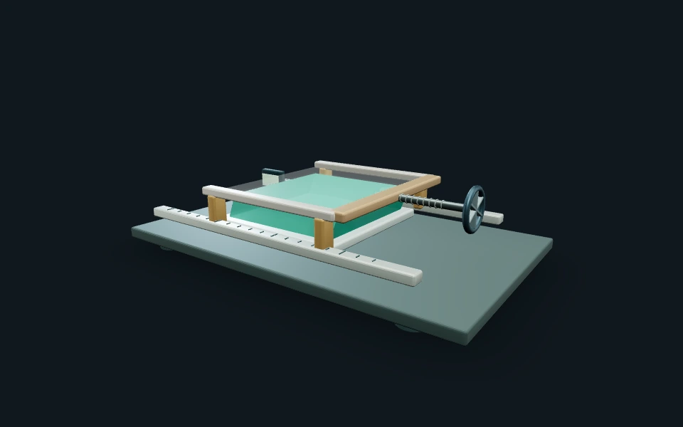 Interactive exploration
Make the same small move at different speeds, park a material-testing carriage, and watch its force change. Explore polymer networks, relaxation, creep and real research images without inventing a breaking rule.
 Interactive exploration
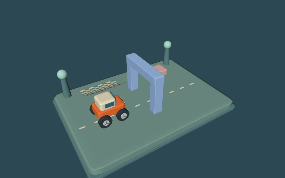
Drive an original little rover behind an arch, turn the camera, and open one pixel of the actual picture. Discover which triangle wins, where its color comes from, and what changes when you add more samples.
Turn once. Count what happens. Discover gear ratios, real-world uses, and why different jobs need different gears.