The shutter is a time window
An exposure gathers light over an interval. It is not an infinitely short instant. In this lab the electronic exposure window is uniform; no moving mechanical shutter curtain is simulated.
Photograph a moving toy, shorten the exposure, and unroll the time behind each row. Compare motion blur, rolling shutter, missed focus and low-light noise using your own saved captures.
Enable JavaScript to change the conditions and run the interactive experiment.
A camera gathers light for a little while. When an image moves during that time, its light can spread across pixels. If different rows gather light at different moments, a straight moving object can also look tilted. Blur and tilt have different causes—and different fixes.
A shorter exposure sharpens the moving stripe, but it still leans. What changed—and what stayed?
Each row gathered motion over less time, but different rows still captured different moments. The full-height center displacement remains vR.
An exposure gathers light over an interval. It is not an infinitely short instant. In this lab the electronic exposure window is uniform; no moving mechanical shutter curtain is simulated.
Our toy image translates horizontally at a constant speed. At 800 image pixels per second, a 1/200-second exposure spans 4 pixels of motion. The feature has its own width, and each detector pixel also covers an area.
A rolling exposure staggers the row intervals. With a 20-millisecond delay from the first row to the last, our full-height stripe shifts 16 pixels from top to bottom. Many row intervals overlap; a scanning beam is not required.
Shorten each exposure to 1/2000 second: its motion extent becomes 0.4 pixels. The 20-millisecond first-to-last delay is unchanged, so the full-height centerline displacement is still 16 pixels.
Global exposure gives the rows a common exposure interval. The sensor can still transfer their stored values in sequence afterward. That transfer alone does not mean the rows captured different moments.
A stationary flat target can remain fuzzy when its image does not converge onto the detector plane. Our separate focus bench changes the ideal sensor distance and circular aperture footprint. Shorter exposure does not move the focus plane.
A longer exposure can collect more detected electrons from a stationary patch. Brightness normalization divides by duration to help compare shapes; display gain can brighten the result. Neither operation creates more collected signal.
The noise loupe samples photon-count variation and independent read noise using a saved seed. A redraw or brightness change keeps the same sample. Take another sample to make a new observation.
The reference detector has 640 columns and 360 rows, numbered from zero. Coordinates describe the final upright image. Relative motion is measured in image pixels per second, not a measured toy speed in meters per second.
For row r, c(r) = (r/359 − 1/2)R; reversing scan changes its sign. Start is c − T/2 and end is c + T/2. R is explicitly the first-to-last center delay, not an unqualified manufacturer readout-time specification.
Per-row motion extent is |v|T. The signed full-height center displacement is vR, with scan direction included. The full capture span is R + T, while the adjacent-row delay is R/359. None of these by itself establishes the frame rate.
The image operator integrates a continuous row signal over the chosen exposure and a one-pixel detector footprint. Toy source pixels are decoded from sRGB into premultiplied linear RGBA and reconstructed as constant cells. Moving foreground coverage and the stationary background are combined in that space. Encoding for display happens last.
Translation is constant, horizontal and parallel to a fixed orthographic image plane. Piecewise-polynomial primitives integrate the reconstructed source exactly, including fractional shifts. This does not represent spinning wheels, acceleration, moving perspective, depth-dependent motion or a general camera-shake kernel.
The calibration bar is eight pixels wide before motion. At four pixels of motion, detector centers at offsets 0, 2, 4 and 6 receive normalized signals 1, 31/32, 1/2 and 1/32. At sixteen pixels of motion the central value is 1/2. The normalized bar area remains eight pixels, with enough image margin.
The full-height calibration bar has the complete vR center displacement. The shorter placard on the toy spans fewer row times. Do not attribute the full-image number to every short edge in the picture.
For the stationary flat target, object distance is 1,000 mm, focal length 8 mm and detector pitch 0.01 mm. Focusing at 500 mm with f/2 produces a geometric footprint diameter of 400/123 ≈ 3.2520 pixels. At f/4 it is half as large. This is a circular footprint diameter, not a Gaussian blur setting.
The flat-target inspector convolves a normalized circular footprint, using 64 × 64 area samples per kernel cell. Diffraction, lens aberrations, color filters, lens breathing, autofocus and portrait-mode processing are omitted. The narrow geometric model does not mean that the smallest possible aperture always gives the sharpest photograph.
The separate stationary patch has an authored expected detected-electron rate of 20,000 per second at f/2 and illumination multiplier 1. Expected count μ = 20,000Tq(2/N)² already includes detection efficiency; it is not an incident-photon rate or a measurement of a real phone.
The patch uses P distributed as Poisson(μ), plus independent zero-mean Gaussian read noise with standard deviation 2 electrons. Before clipping, the mean is μ, variance is μ + 4 and input SNR is μ/√(μ + 4). At 10, 100 and 400 expected electrons the SNRs are approximately 2.673, 9.806 and 19.901.
A phone may combine frames and apply denoising, sharpening, stabilization or other processing. Our display gain is not a complete ISO model, and our single-exposure image is not a reconstruction of a particular phone pipeline. A corrected source image is an estimate, not proof that arbitrary lost information can be recovered.
A short exposure can reduce subject-motion blur. It does not by itself remove row-time distortion or fix missed focus.
Timing matters when cameras measure moving objects. Exposure synchronization, row timing and geometric calibration are separate design questions.
Steadying the phone can reduce camera motion. Scene light, focus and computational processing still matter; this is not a universal settings recipe.
Keep the toy on a table and clear a short path. Use ordinary room light. You do not need a moving vehicle, a powered fan or bright light aimed into eyes.
Rest the camera securely. Frame the toy and a stationary background. A moving camera can blur both; a moving toy can blur while the background stays sharp.
Move the toy slowly across the same short path. Take a picture. The aim is a visible comparison, not a speed contest. Use the supplied capture lab if no camera is available.
If your camera exposes shutter controls, compare two durations under the same lighting. Automatic phones may change several settings or combine frames; record that limitation instead of claiming a controlled experiment.
Label the images with the settings you know. Compare a moving edge and a stationary edge. Do not invent a row delay from the amount of blur; they are different quantities.
Photograph a stationary print. If manual focus is available, compare correct and intentionally nearer focus. Otherwise use the flat-print inspector. Do not use this as an eyesight test.
Separate motion blur, missed focus and any apparent geometric distortion. State which settings were controlled and which were automatic or unknown. A photo alone does not always identify one cause.
Which comparison isolates motion, and which settings could still be changing together?
Automatic cameras and hand motion are not calibrated laboratory controls. The optional activity does not measure a real sensor’s scan delay or diagnose a lens.
Shorten the motion smear. Motion extent is speed × exposure duration.
4 pixels 800 × 0.005 = 4 image pixels.
Different rows still capture different moments. Short row exposures and a nonzero first-to-last delay coexist.
No: the exposure intervals matter. All rows can share an exposure interval and transfer their stored values later.
Focus setting Geometric defocus survives when the scene stops.
No: the existing signal and noise were scaled. A display operation does not create collected electrons.
A finite random sample can differ from its expectation. A distribution describes repeated observations; a finite draw need not equal its expectation.
Processed correction estimates The paper labels c and d as algorithmic corrections.
Manufacturer explanation of exposure intervals and stored-value readout. Device-specific specifications are not generalized.
Basler · Electronic shutter typesPrimary rolling-shutter geometry paper. Our parallel translation model is independently derived and narrower.
Meingast, Geyer & Sastry · Geometric modelsPrimary sensor characterization standard; model assumptions are explicit. This lab is not an EMVA-compliant measurement.
EMVA · 1288 Linear, release 4.0Course-author imaging notes support the noise/observation distinction; no source diagrams are redistributed.
Wetzstein · Imaging noise notesSource-owned rendering reference. This implementation uses exact integration for a bounded reconstructed image field.
Pharr, Jakob & Humphreys · Camera interfaceThe geometric cone diameter is derived from the thin-lens relation; diffraction and aberrations are excluded.
OpenStax · Thin lensesSource definition of sRGB transfer functions. Display clipping and encoding occur after the signal calculation.
W3C · CSS Color 4 conversion codeFigures 12 and 16, original complete JPEGs, CC BY 4.0. They do not calibrate the authored simulation or establish a universal correction capability.
Ye and colleagues · Sensors 2026Independent subject review is pending.
Read the sources and model assumptionsSlide an object toward a lens. Follow the rays, find a sharp image, and discover the moment a camera becomes a magnifier.
 Interactive exploration
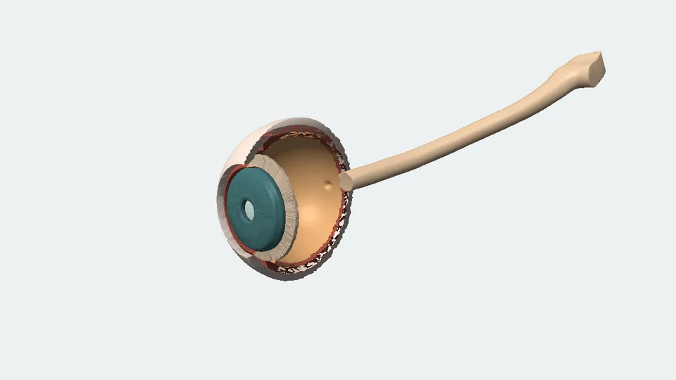
Open a sourced 3D eye, move a target nearer, and catch the moment its light comes together. Then discover why a smaller pupil is different from better focus.
 Interactive exploration
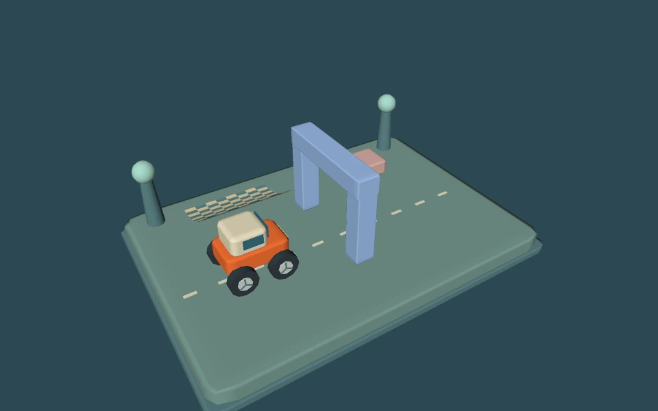
Drive an original little rover behind an arch, turn the camera, and open one pixel of the actual picture. Discover which triangle wins, where its color comes from, and what changes when you add more samples.